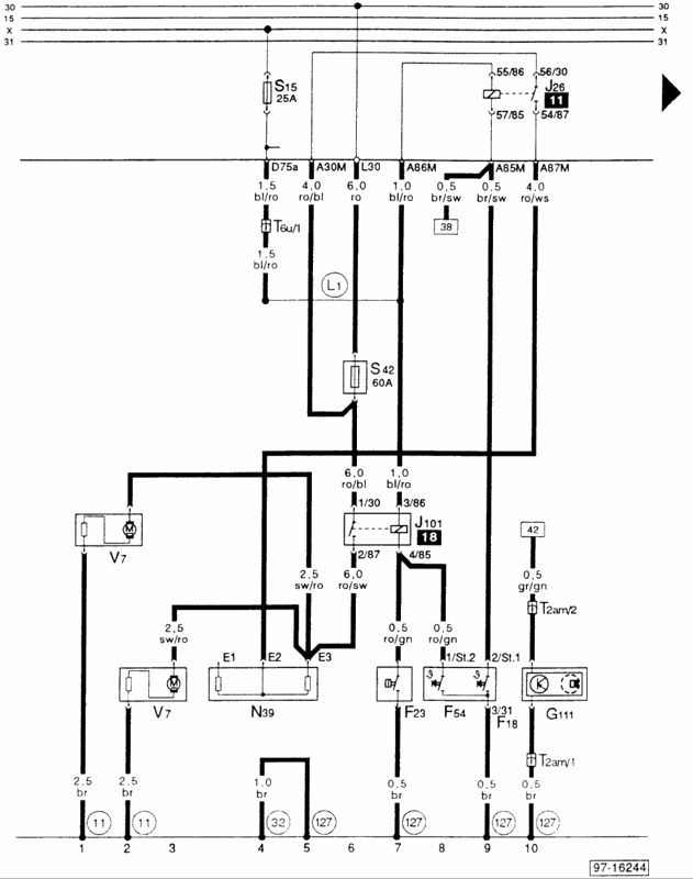
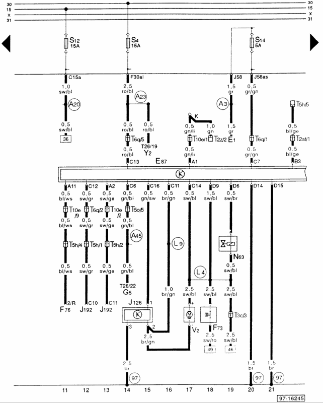
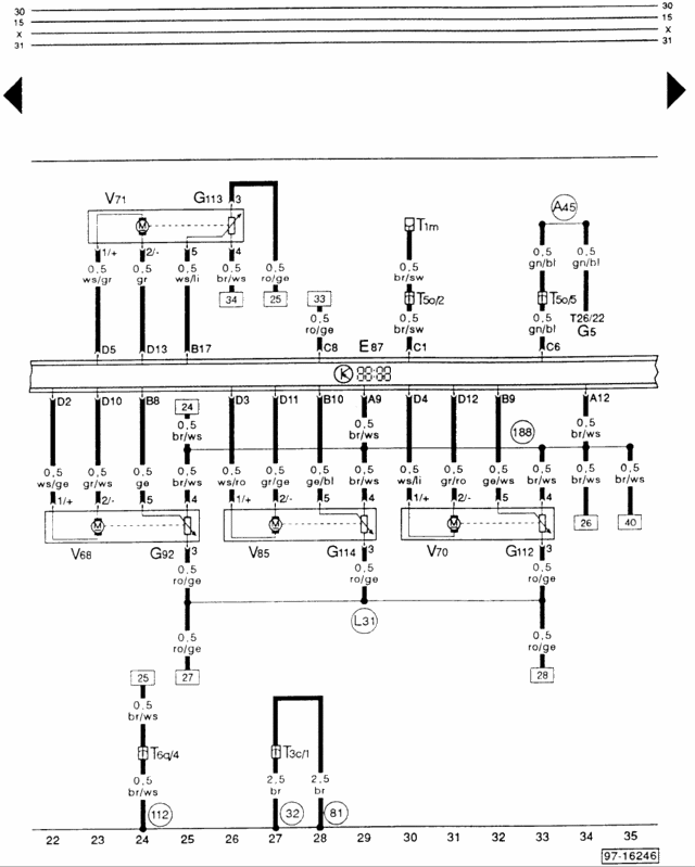
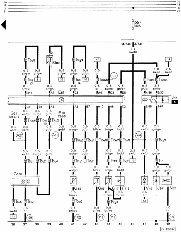
O Esquema do Módulo AC (Audi 80?) está em 4 Partes... nos esquemas, o E87 é o referido Módulo. Se achares as Fotos muito pequenas, vais ás propriedades de cada uma e Copy/Paste para o teu Browser:
COMPONENT
F23 = A/C Refrigerant High Pressure Switch
G111 = A/C Compressor Speed Sensor
F18 = Coolant Fan Control (FC) Thermoswitch
F54 = Coolant Fan Control (FC) Thermoswitch
J26 = Coolant Fan Control (FC) Relay
N39 = Coolant Fan Control (FC) Series Resistance
V7 = Coolant Fan
S42 = Fuse For Coolant Fan, in Adapter B
J101 = Second Speed Coolant Fan Control (FC) Relay
CONNECTORS
T2am = Wire Connector, double. green, near compressor
T6u = Wire Connector, 6 Point, green, behind instrument panel, left
GROUNDS CONNECTION
NOTE: Grounds connections are indicated on the diagram by a numeric code inside a circle.
11 - Ground connection, in battery box
32 - Ground connection behind instrument panel, left
127 - Ground connection -1-, in A/C compressor wiring harness
HARNESS SPLICES
NOTE: Harness splices are points inside a wiring harness where two or more wires are crimped and/or soldered together. Harness splices are indicated on the diagrams by an alphanumeric code inside a circle.
L1 - Plus connection (75), in A/C wiring harness
COMPONENTS
E87 = A/C Control Head
F73 = A/C Refrigerant Low Pressure Switch
Y2 = Digital Clock
F76 = Engine Coolant Temperature (ECT) Electronic Thermoswitch
J126 = Fresh Air Blower Control Module
N63 = Fresh Air , Recirculating Flap Two-Way Valve
V2 = Fresh Air Blower
E1 = Light Switch
J192 = MFI Engine Control Module (ECM)
G5 = Tachometer
K - Wire Distributer For Data Link Connector(DLC); Terminal K
CONNECTORS
T2z = Wire Connector, double, white, in Plenum, Near Relay Panel (Data Link Connector)
T2at = Wire Connector, double, black, behind instrument panel, center
T3c = Wire Connector, 3 Point, brown, behind instrument panel, center
T5h = Wire Connector, 5 Point, red, behind instrument panel, left
T5o = Wire Connector, 5 Point, red, behind instrument panel, center
T6q = Wire Connector, 6 Point, red, behind instrument panel, center
T10e = Wire Connector, 10 Point, red, behind instrument panel, center
T26 = Wire Connector, 26 Point, yellow, on instrument cluster
GROUNDS CONNECTION
NOTE: Grounds connections are indicated on the diagram by a numeric code inside a circle.
97 - Ground connection -1-, in A/C wiring harness
HARNESS SPLICES
NOTE: Harness splices are points inside a wiring harness where two or more wires are crimped and/or soldered together. Harness splices are indicated on the diagrams by an alphanumeric code inside a circle.
A3 - Plus connection (58), in instrument panel wiring harness
A20 - Wire connection (15a), in instrument panel wiring harness
A23 - Wire connection (30al), in instrument panel wiring harness
A45 - Wire connection (RPM signal), in instrument panel wiring harness
L4 - Wire connection (75al), in A/C wiring harness
L6 - Wire connection -1-, in A/C wiring harness
COMPONENTS
E87 = A/C Control Head
V71 = Air Flow Flap Motor
G113 = Back Pressure Flap Motor Potentiometer
G112 = Central Flap Motor Potentiometer
V70 = Central Air Flap Motor
G114 = Footwell , Defrost Flap Motor Potentiometer
V85 = Footwell I Defrosted Flap Motor
G5 = Tachometer
G92 = Temperature Regulator Flap Motor Potentiometer
V68 = Temperature Regulator Flap Motor
CONNECTORS
T1m = Wire Connector, single, red, behind instrument panel, left
T3c = Wire Connector, 3 Point, brown, behind instrument panel, center
T5o = Wire Connector, 5 Point, red, behind instrument panel center
T6q = Wire Connector, 6 Point, behind instrument panel, center
T26 = Wire Connector, 26 Point, yellow, on instrument cluster
GROUNDS CONNECTION
NOTE: Grounds connections are indicated on the diagram by a numeric code inside a circle.
81 - Ground connection -1-, in instrument panel wiring harness
97 - Ground connection -1-, in A/C wiring harness
112 - Ground connection -2-, in A/C wiring harness
188 - Ground connection -3-, in A/C wiring harness
HARNESS SPLICES
NOTE: Harness splices are points inside a wiring harness where two or more wires are crimped and/or soldered together. Harness splices are indicated on the diagrams by an alphanumeric code inside a circle.
A45 - Wire connection (RPM signal), in instrument panel wiring harness
L31 - Wire connection ( 5 Volts), in A/C wiring harness
COMPONENTS
E87 = A/C Control Head
F118 = A/C Refrigerant High Pressure Switch
J44 = A/C Clutch Relay
N25 = A/C Clutch
V42 = Fan For Interior Temperature Sensor
G89 = Fresh Air intake Duct Temperature Sensor
E20 = Instrument Panel Light Dimmer Switch
G56 = Interior Temperature Sensor, in instrument panel
G86 = Interior Temperature Sensor, in Headliner
G106 = Outside Air Temperature Display
G17 = Outside Air Temperature Sensor
J201 = Protection Diode
G21 = Speedometer
CONNECTORS
T1n = Wire Connector, single green, near compressor
T2t = Wire Connector, double, brown, behind instrument panel, left
T2u = Wire Connector, double, red, behind instrument panel, left
T3c = Wire Connector, 3 Point, brown, behind instrument panel, center
T5g = Wire Connector, 5 Point, green, connector station in auxiliary relay panel
T5l = Wire Connector, 5 Point, yellow, on instrument cluster
T5o = Wire Connector, 5 Point, red, behind instrument panel, center
T6q = Wire Connector, 6 Point, red, behind instrument panel, center
T10e = Wire Connector, 10 Point, red, behind instrument panel, center
T26 = Wire Connector, 26 Point, yellow, on instrument cluster
T26a = Wire Connector, 26 Point, blue, on instrument cluster
GROUNDS CONNECTION
NOTE: Grounds connections are indicated on the diagram by a numeric code inside a circle.
29 - Ground connection, near compressor
112 - Ground connection -2-, in A/C wiring harness
199 - Ground connection -2-, in instrument panel wiring harness
HARNESS SPLICES
NOTE: Harness splices are points inside a wiring harness where two or more wires are crimped and/or soldered together. Harness splices are indicated on the diagrams by an alphanumeric code inside a circle.
A19 - Wire connection (58d), in instrument panel wiring harness
A27 - Wire connection (speed signal), in instrument panel wiring harness
A34 - Wire connection (75x), in instrument panel wiring harness
L2 - Wire connection, in A/C wiring harness


